| |||
| |||
| |||
|
 Sven Pawletta, Thorsten Pawletta, Hochschule Wismar - University of
Technology, Business & Design
Sven Pawletta, Thorsten Pawletta, Hochschule Wismar - University of
Technology, Business & Design
| |||
| |||
| |||
|
The main goal of this thesis is to realize and
develop control strategies of a mobile robot model using MATLAB® environment.
These strategies should be realized with the help of Simulink® and Stateflow®
tools. Program's code for the model should be generated automatically by
MATLAB® using Real-Time Workshop® and other necessary programs.
Robotics is a special engineering science
dealing with designing, modelling, controlling and robots' utilization.
Nowadays robots accompany people in everyday life and take over their daily
routine procedures. The range of robots' utilization is very wide, from toys
through office and industrial robots finally to very sophisticated ones needed
for space exploration. To build our robot we used elements from LEGO®
Mindstorms Robotics Invention System 1.5, and LEGO® Mindstorms Robotics
Discovery Set. We run all our programs on this robot construction.
Caterpillars, a bumper and a part of chassis were taken from LEGO®
Constructopedia. Other parts of the robot are based on our project.Assumptions:
Introduction
What is mainly used for robots' controlling are PLC
drivers (Programmable Logic Controllers) or other specialized regulators. The
aim of our thesis is to realize more flexible control strategies of a mobile
robot model by means of PC computer. In order to accomplish this we will use:
Simulink®, Stateflow® and Real-Time Workshop® enclosed in MATLAB®. The model
of robot will be built via LEGO® Mindstorms sets: Robotics Invention System
1.5 and Robotics Discovery.
Testing and the controlling realization with
the use of the industrial type of robot would be very expensive. We decided to
use the LEGO® type because it is quite cheap and despite its simplicity and
limited possibilities it allows to present and understand the idea of mobile
robots' controlling. During the levels of exemplary strategies we will have
two kinds of sensors at our disposal (touch sensor and light sensor) and three
motors. At the very beginning we want to create a simple instance of control
strategy and then, through the next stages and examples, to expand it much
more. In future, on the basis of our work and examples found here, there will
be laboratory classes about robots' programming conducted. Our goal is to form
the set of examples of various level of difficulty and complexity. In our
opinion, what will make the way to understand the idea of robots' controlling
with the aid of MATLAB® the shortest is the analysis of the aforementioned
examples.
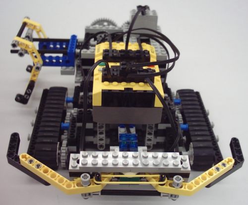
Construction of the robot
Our
construction requires four touch sensors and three motors. Two touch sensors
are in the bumper in front of the robot (connected to input port 1 and 3) to
detect obstructions, and two touch sensors are in the arm to detect arm
position. Because of the limitation of RCX inputs touch sensors in arm are
connected in a parallel way, and attached to the input port 2. These sensors
can detect only extreme position of the arm (arm inside or arm outside), and
in both of these positions generate the same event. Because of this limitation
the starting positions of arm is inside. To drive the robot we used two motors
connected to output ports 1 and 3. Third motor is used to change arm position
and is connected to output port 2.
Stateflow® is a powerful graphical design and development tool for complex control and supervisory logic problems. Stateflow® provides clear, concise descriptions of complex system behaviour using finite state machine theory, flow diagram notations, and state-transition diagrams. Stateflow® is used together with Simulink® and optionally with the Real-Time Workshop® (RTW), all running on top of MATLAB®. MATLAB® provides access to data, high-level programming, and visualization tools. Simulink® supports development of continuous-time and discrete-time dynamic systems in a graphical block diagram environment. Stateflow® diagrams are incorporated into Simulink®models to enhance the new event-driven capabilities in Simulink® (such as conditionally executed subsystems and event detection).
Real-Time Workshop® allows to convert Simulink®
model containing Stateflow® machine to the C code using Real-Time Workshop
Embedded Coder®. ECRobot (Embedded Coder Robot) is a simple example of a
custom target based on the Real-Time Workshop Embedded Coder®and generates
production code for embedded systems like LegOS. The C code generates by
Real-Time Workshop Embedded Coder® is compiled by the GCC cross-compiler for
the Hitachi microcontroller, h8300-hms-gcc. Programs generated by the ECRobot
target run on the Robot Command System (RCX) module of the LEGO® Mindstorms
Robotics Invention System 1.5.
The inputs to the model come from two device driver blocks, Touch_Left and Touch_Right. Both touch sensors blocks read sensor values on every time step of the model. The expected values are 1 (sensor activated) or 0 (sensor not activated). These values function as events within the Control block. Signals from sensors are multiplexed with the software timer signal. Maximum number of input blocks is three.
The outputs from the model come from two device driver blocks, Motor_right and Motor_left. Motor_right and Motor_left blocks are characterised by the direction and speed values. The speed value is an unsigned 8-bit constant setting in Speed block. The unsigned 8-bit directional value is either 1 (forward), 2 (backward), 3 (brake) or 0 (stop). Maximum number of output blocks is three.
Software timer is a feedback loop which consists of the Constant1, Sum, and Unit Delay blocks generates a "square wave" that toggles from 1 to 0 on each model step. This signal functions as a software timer for the Control block, which counts rising edges as events. The software timer is not true real-time clock. Its functions are better understood as an event generator for the Control block. Event timing method was chosen due to limitations of the LegOS kernel.
The main core of the Control block is to
determine directional control values to be transmitted to the motors device
driver blocks. Control block includes a Stateflow® chart. Stateflow® chart
represents control strategy of the robot.
One of our exemplary control strategy for the robot is shown below and contains among other short task description and our suggested solution.
Task description:
The robot should execute the following actions:
What is mainly used for robots' controlling are
PLC drivers (Programmable Logic Controllers) or other specialized regulators.
The aim of our thesis was to realize more flexible control strategy of a
mobile robot model by means of PC computer. The goal of our thesis was to
accomplish and present various options of the mobile robot's model control
strategies with the use of Simulink®, Stateflow® and Real-Time Workshop®
included in the MATLAB® package. On the basis of the aforementioned software
we formed the set of exemplary programmes presenting different strategies of
the robot controlling. The set includes instances with various difficulty and
complexity levels. During the strategies' realization we attempted at
utilizing maximally all possibilities of our robot. The strategies that we
describe at the beginning show different kinds of drive steering via two
engines. From simple instances we moved to more difficult and advanced with
the aim of modelling idea with the help of Stateflow® understanding. The
analysis and investigation into the above mentioned examples should be helpful
in the following development of the model steering with the use of sensors. In
case of some examples we present two options of one strategy realization. The
reason behind this logic is to pay a special attention to the opportunities
offered by Stateflow®modelling.

